
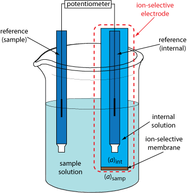
Shown here is a schematic diagram of a typical potentiometric cell that includes a membrane electrode (in this case, an ion-selective membrane). The membrane separates the sample solution, which contains the analyte at an activity of (aA)samp, from an internal solution containing the analyte with an activity of (aA)int.

The electrochemical cell includes two reference electrodes: one immersed in the ion-selective electrode’s internal solution and one in the sample solution. The cell potential, therefore, is
Ecell = (Eref)int – (Eref)samp + Emem + Ej
where Emem is the potential across the membrane. Because the junction potential and the potential of the two reference electrodes are constant, any change in Ecell is a result of a change in the membrane’s potential. In turn, the membrane potential depends on the analyte’s concentration in the sample solution and the internal solution; as its concentration in the internal solution is fixed, any change in the membrane’s potential is due to the concentration of analyte in the sample.