
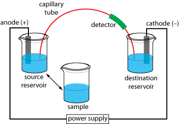
The basic instrumentation for capillary electrophoresis is shown here and includes a power supply for applying the electric field, anode and cathode compartments containing reservoirs of the buffer solution, a sample vial containing the sample, the capillary tube, and a detector. The sample and the source reservoir are switched when making injections.

The illustration below shows a cross-section through a typical capillary tube. Most capillary tubes are made from fused silica coated with a 15–35 μm layer of polyimide to give it mechanical strength. The inner diameter is typically 25–75 μm—smaller than the internal diameter of a capillary GC column—with an outer diameter of 200–375 μm.

The capillary column’s narrow opening and the thickness of its walls are important. When an electric field is applied to the buffer solution within the capillary, current flows through the capillary. This current leads to the release of heat—what we call Joule heating. The amount of heat released is proportional to the capillary’s radius and the magnitude of the electrical field. Joule heating is a problem because it changes the buffer solution’s viscosity, with the solution at the center of the capillary being less viscous than that near the capillary walls. Because a solute’s electrophoretic mobility depends on viscosity, solute species in the center of the capillary migrate at a faster rate than those near the capillary walls. The result is an additional source of band broadening that degrades the separation. Capillaries with smaller inner diameters generate less Joule heating, and capillaries with larger outer diameters are more effective at dissipating the heat.