
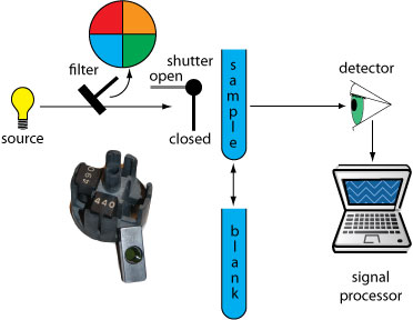
The illustration below is a diagram of a simple filter photometer, which uses an absorption filter (shown here) or interference filter to isolate a band of radiation. The analyst either inserts a removable filter or the filters are placed in a carousel, an example of which is shown in the photographic inset.

A filter photometer has a single optical path between the source and detector, and is called a single-beam instrument. The instrument is calibrated to 0% T while using a shutter to block the source radiation from the detector. After opening the shutter, the instrument is calibrated to 100% T using an appropriate blank. The blank is then replaced with the sample and its transmittance measured. Because the source’s incident power and the sensitivity of the detector vary with wavelength, the photometer must be recalibrated whenever the filter is changed.
Photometers have the advantage of being relatively inexpensive, rugged, and easy to maintain. Another advantage of a photometer is its portability, making it easy to take into the field. Disadvantages of a photometer include the inability to record an absorption spectrum and the source’s relatively large effective bandwidth, which limits the calibration curve’s linearity